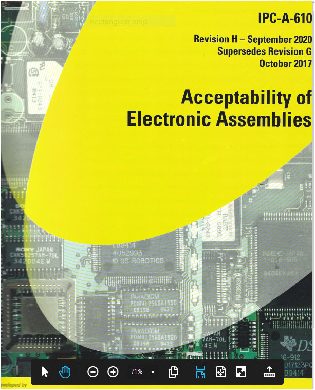
IPC-A-610H - Acceptability of Electronic Assemblies
IPC-610H is the most widely used document for electronic assembly.
The document defines the latest IPC acceptance criteria for class 1 and 2 electronic assemblies.
Introduction: IPC CIS Policies and Procedures (Required)
IPC CIS Policies and Procedures Version 7.3 defines the IPC Mission Statement, Interpretation of Policies and Procedures, Prerequisites and Fees, Assessment Methods, and IPC Certification Terms.
Module 1: Introduction, Forward, Applicable Documents and Handling (Required)
Module 1 introduces the IPC-610H, product quality definitions, terms and definitions, requirements and flowdown, personnel proficiency and inspection methodology.
Module 2: Soldering and High Voltage
Module 2 addresses IPC Soldering Acceptability Requirements. It defines soldering anomalies common to SMT and Through-Hole connections using either tin-lead or lead-free solder.
Also addressed are the high voltage criteria specified in procurement documentation for wires and leads attached to terminals, bare wires and through-hole connections.
Module 3: Component Damage and PCBs
This module identifies potential loss of metallization on SMT chip resistors, leaded and leadless devices, ceramic chip carriers, and damage to connectors, relays, press-fit and backplane connector pins and threaded hardware.
It covers acceptability requirements for cleanliness of assemblies with any electrical interfacing surfaces. Criteria are applied to both the primary and secondary sides of the PCB. It also stresses the importance of contaminant removal and its verification.
Module 4: Terminals (Requires Module 2)
This section addresses wire and component lead mechanical connections used in attachment to turret, bifurcated, rolled and flared flange terminals. It identifies common insulation damage and installation clearance problems, conductor damage and terminal solder requirements.
Module 5: Through-Hole Technology (Requires Modules 2 and 3)
Module 5 addresses hardware, adhesive, forming, mounting, termination and soldering of through-hole components. It also includes solder requirements for supported and unsupported holes and jumper wires.
Module 6: Surface Mount Technology (Requires Modules 2 and 3)
Module 6 covers acceptability requirements for surface mount assemblies. This includes staking adhesive and its application. SMT termination criteria are also specified for surface mounted chips, MELFs, castellated terminations, gull wing and J-leads, surface mount arrays and jumper wires.
Module 7: Hardware
This section addresses several types of hardware used in mounting electronic devices to printed circuit boards (PCBs). These include screws, nuts, bolts, washers, fasteners, and clips. Its focus is on visual inspection of proper tightness and component damage caused during component mounting.
Students complete review questions at the conclusion of each Module.
Module 1 includes a Closed Book Exam. Modules 2-8 are Open Book.
Minimum passing score for all exams is 70%.
Course Inquiry / Questions